
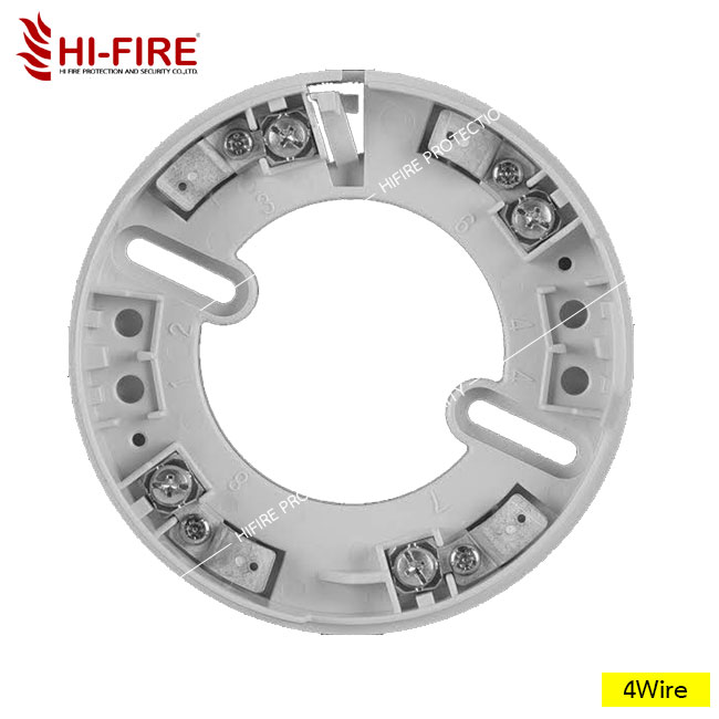
ฐานสำหรับอุปกรณ์ตรวจจับเปลวไฟ ฐานติดลอย 4 ขั้ว รุ่น FZBO1 3-4 ยี่ห้อ NOHMI
| รหัสสินค้า | SKU-00059 |
| หมวดหมู่ | อุปกรณ์ระบบไฟอลาม |
| ราคา | 350.00 บาท |
| สถานะสินค้า | พร้อมส่ง |
| ลงสินค้า | 9 มิ.ย. 2566 |
| อัพเดทล่าสุด | 8 ส.ค. 2568 |
| คงเหลือ | 1 ชิ้น |
| จำนวน | ชิ้น |
หยิบลงตะกร้า

Tags : อุปกรณ์ไฟอลาม, นอมิ, ตู้ควบคุมระบบไฟอลาม, Nohmi, fire Alarm, Alarm Bell, แจ้งเตือนเหตุเพลิงไหม้, กระดิ่งแจ้งเตือนเหตุ, Telephone Handset, Waterproof fire Alarm, Heat Delector, Smoke Delector, Location Lamp, ตรวจจับควัน, ตรวจจับความร้อน, แมนวล, ดับเพลิง, เพลิงไหม้
รายละเอียดสินค้า
จำหน่าย ฐานสำหรับอุปกรณ์ตรวจจับเปลวไฟ ฐานติดลอย 4 ขั้ว รุ่น FZBO1 3-4 ยี่ห้อ NOHMI ในราคาปลีก-ส่ง ติดต่อ บริษัท ไฮไฟร์โพรเทคชั่น แอนด์ ซีเคียวริตี้ จำกัด สายด่วน 02-125-7009 ขายส่งอุปกรณ์ ไฟอลาม ทุกชนิด
|
เงื่อนไขอื่นๆ

วิธีการชำระเงิน
ธนาคารกสิกรไทย
เลขที่บัญชี 158-8-65267-6
ชื่อบัญชี บจก.ไฮไฟร์โพรเทคชั่น แอนด์ ซีเคียวริตี้
ชำระเงินผ่านธนาคาร
นโยบายการเปลี่ยนหรือคืนสินค้า
ไม่สามารถเปลี่ยนหรือคืนสินค้า
ระบบสมาชิก
เมื่อสั่งซื้อสินค้ากับเรา บจก.ไฮไฟร์โพรเทคชั่นแอนด์ซีเคียวริตี้ ครบ 5 ครั้ง ครั้งที่ 6 ส่งฟรี แอดไลน์ @066aesmf
 Hi-Fire Protection and Security
สมัครสมาชิกร้านนี้ เพื่อรับสิทธิพิเศษ
 ธ.กสิกรไทย
▲
▼
รายการสั่งซื้อของฉัน
รายการสั่งซื้อของฉัน
ข้อมูลร้านค้านี้

Hi-Fire Protection and Security
Hi-Fire Protection and Security จำหน่ายอุปกรณ์ป้องกันและระงับเหตุเพลิงไหม้ อุปกรณ์เซฟตี้ อุปกรณ์กู้ภัย และอุปกรณ์เพื่อความปลอดภัยในอาคารบ้านเรือนทุกชนิด คัดสรรสินค้าที่ได้รับมาตรฐานเท่านั้น
เบอร์โทร : 0839899311
อีเมล : hifire.protect@gmail.com
อีเมล : hifire.protect@gmail.com
ส่งข้อความติดต่อร้าน
เกี่ยวกับร้านค้านี้
ค้นหาสินค้าในร้านนี้
ค้นหาสินค้า
สินค้าที่ดูล่าสุด
บันทึกเป็นร้านโปรด
Join เป็นสมาชิกร้าน
แชร์หน้านี้
แชร์หน้านี้
↑
TOP เลื่อนขึ้นบนสุด
TOP เลื่อนขึ้นบนสุด
สินค้าในตะกร้า ({{total_num}} รายการ)

ขออภัย ขณะนี้ยังไม่มีสินค้าในตะกร้า
ราคาสินค้าทั้งหมด
฿ {{price_format(total_price)}}
- ฿ {{price_format(discount.price)}}
ราคาสินค้าทั้งหมด
{{total_quantity}} ชิ้น
฿ {{price_format(after_product_price)}}
ราคาไม่รวมค่าจัดส่ง
➜ เลือกซื้อสินค้าเพิ่ม